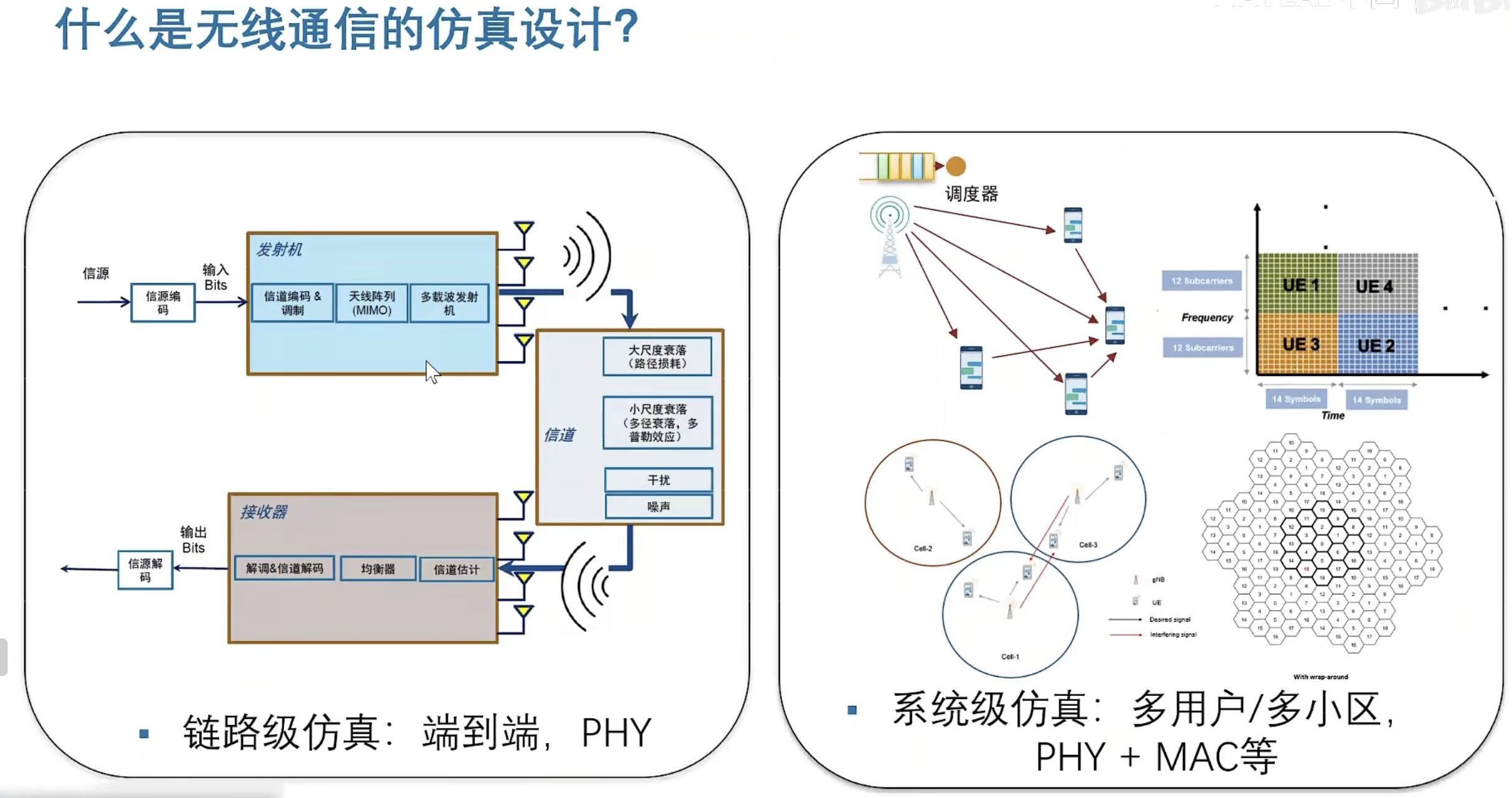
基于MATLAB R2022b版软件学习!
【官方】2023小迈步之通信系统设计——从基础到 AI+(上)_哔哩哔哩_bilibili


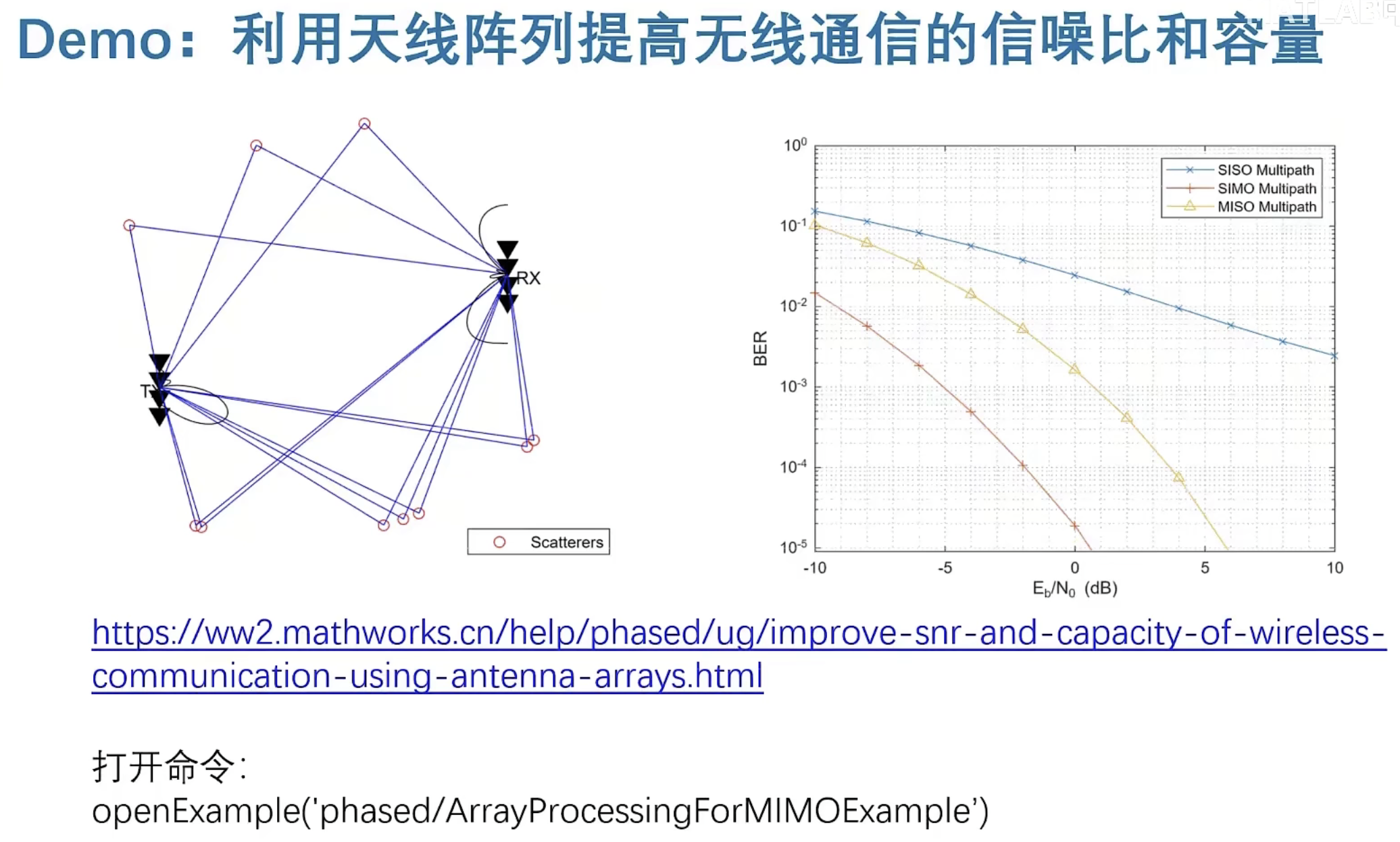
Improve SNR and Capacity of Wireless Communication Using Antenna Arrays
利用天线阵列提高无线通信的信噪比和容量
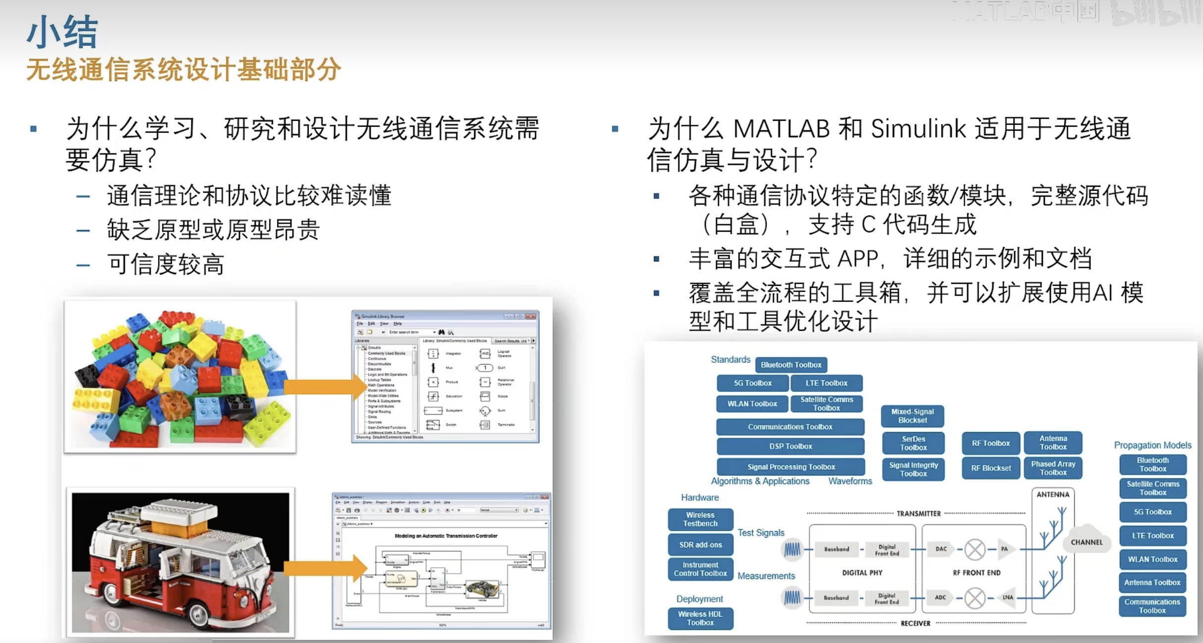
The goal of a wireless communication system is to serve as many users with the highest possible data rate given constraints such as radiation power limit and operating budget. To improve the data rate, the key is to improve the signal to noise ratio (SNR). To serve more users, the key is to reuse the resources. Over the last several decades, numerous algorithms have been adopted to improve the SNR and reuse the resources in time, frequency, and coding spaces. This example shows how the adoption of antenna arrays can help improve the SNR and capacity of a wireless link.
无线通信系统的目标是在给定诸如辐射功率限制和运行预算等限制条件下,以尽可能高的数据速率为尽可能多的用户服务。提高数据传输速率的关键是提高信噪比(SNR)。为更多的用户服务,关键是资源的重用。在过去的几十年里,人们采用了许多算法来提高信噪比,并在时间、频率和编码空间上重用资源。本例展示了天线阵列的采用如何有助于提高无线链路的信噪比和容量。
Introduction
Antenna arrays have become part of the standard configuration in 5G wireless communication systems. Because there are multiple elements in an antenna array, such wireless communications systems are often referred to as multiple input multiple output (MIMO) systems. Antenna arrays can help improve the SNR by exploring the redundancy across the multiple transmit and receive channels. They also make it possible to reuse the spatial information in the system to improve the coverage.
天线阵列已经成为5G无线通信系统标准配置的一部分。由于天线阵列中有多个元件,因此这种无线通信系统通常被称为多输入多输出(MIMO)系统。天线阵列可以通过探索多个发射和接收通道的冗余来帮助提高信噪比。它们还可以重用系统中的空间信息,以提高覆盖率。
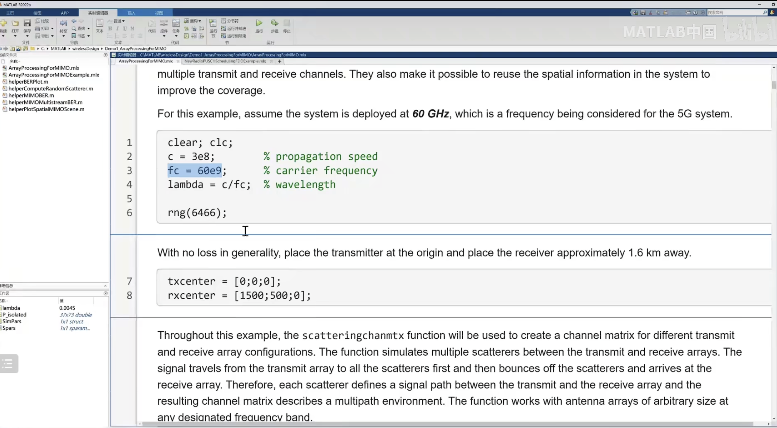
For this example, assume the system is deployed at 60 GHz, which is a frequency being considered for the 5G system.
对于本例,假设系统部署在60 GHz,这是5G系统的频率。
c = 3e8; % propagation speed 传播速度
fc = 60e9; % carrier frequency 载波频率
lambda = c/fc; % wavelength 波长
rng(6466);
With no loss in generality, place the transmitter at the origin and place the receiver approximately 1.6 km away.
在一般无损失的情况下,将发射机放置在原点,接收机放置在大约1.6公里外。
txcenter = [0;0;0];
rxcenter = [1500;500;0];
Throughout this example, the scatteringchanmtx function will be used to create a channel matrix for different transmit and receive array configurations. The function simulates multiple scatterers between the transmit and receive arrays. The signal travels from the transmit array to all the scatterers first and then bounces off the scatterers and arrives at the receive array. Therefore, each scatterer defines a signal path between the transmit and the receive array and the resulting channel matrix describes a multipath environment. The function works with antenna arrays of arbitrary size at any designated frequency band.
在本例中,将使用scatteringchanmtx函数为不同的发射和接收阵列配置创建通道矩阵。该函数模拟发射和接收阵列之间的多个散射器。信号首先从发射阵列传播到所有散射体,然后从散射体反弹到接收阵列。因此,每个散射器定义了发射和接收阵列之间的信号路径,得到的信道矩阵描述了一个多路径环境。该功能适用于任何指定频带上任意大小的天线阵列。
Improve SNR by Array Gain for Line of Sight Propagation
利用阵列增益提高视距传播的信噪比
The simplest wireless channel is a line of sight (LOS) propagation. Although simple, such channels can often be found in rural areas. Adopting an antenna array under such situations can improve the signal to noise ratio at the receiver and in turn improve the communication link's bit error rate (BER).
最简单的无线信道是视线(LOS)传播。这种渠道虽然简单,但在农村地区往往可以找到。在这种情况下,采用天线阵列可以提高接收机的信噪比,进而提高通信链路的误码率。
SISO LOS Channel
单输入单输出视距信道
Before discussing the performance of a MIMO system, it is useful to build a baseline with a single input single output (SISO) communication system. A SISO LOS channel has a direct path from the transmitter to the receiver. Such a channel can be modeled as a special case of the multipath channel.
在讨论MIMO系统的性能之前,用单输入单输出(SISO)通信系统建立一个基线是很有用的。单通道单通道LOS信道具有从发射机到接收机的直接路径。这样的信道可以建模为多路径信道的一种特殊情况。
[~,txang] = rangeangle(rxcenter,txcenter);
[~,rxang] = rangeangle(txcenter,rxcenter);
txsipos = [0;0;0];
rxsopos = [0;0;0];
%helperPlotSpatialMIMOScene(txsipos,rxsopos,txcenter,rxcenter,NaN)
g = 1; % gain for the path 信道增益
sisochan = scatteringchanmtx(txsipos,rxsopos,txang,rxang,g); %视距的信道,假设为1
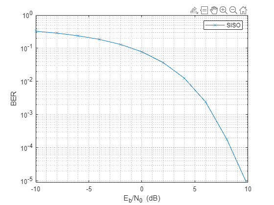
Using BPSK modulation, the bit error rate (BER) for such a SISO channel can be plotted as
使用BPSK调制,这种SISO信道的误码率(BER)可以绘制为
Nsamp = 1e6;
x = randi([0 1],Nsamp,1); %随机生成10的6次方个0和1的数列信号作为物理层数据源
ebn0_param = -10:2:10; %信噪比范围在-10到10之间
Nsnr = numel(ebn0_param);
ber_siso = helperMIMOBER(sisochan,x,ebn0_param)/Nsamp; %信道,输入数据,预编码矩阵 BPSK 除以采样率获取ber平均值
helperBERPlot(ebn0_param,ber_siso);
legend('SISO')
SIMO LOS Channel
单输入多输出(多接收天线)
With the baseline established for a SISO system, this section focuses on the single input multiple output (SIMO) system. In such a system, there is one transmit antenna but multiple receive antennas. Again, it is assumed that there is a direct path between the transmitter and the receiver.
在为SIMO系统建立了基线之后,本节将重点介绍单输入多输出(SIMO)系统。在这种系统中,有一个发射天线,但有多个接收天线。同样,假设发射机和接收机之间有一条直接路径。
Assume the receive array is a 4-element ULA with half-wavelength spacing, then the SIMO channel can be modeled as
假设接收阵列为四天线阵列单元半波长间隔的ULA(均匀线性阵),则SIMO信道可以建模为

rxarray = phased.ULA('NumElements',4,'ElementSpacing',lambda/2);
rxmopos = getElementPosition(rxarray)/lambda;
simochan = scatteringchanmtx(txsipos,rxmopos,txang,rxang,g); %信道矩阵 行为发射天线数量,列为接收天线数量 间隔为半个波长,这几个值具有相干性
In the SIMO system, because the received signals across receive array elements are coherent, it is possible to steer the receive array toward the transmitter to improve the SNR. Note that this assumes that the signal incoming direction is known to the receiver. In reality, the angle is often obtained using direction of arrival estimation algorithms.
在SIMO系统中,由于跨接收阵列单元的接收信号是相干的,因此可以将接收阵列转向发射机以提高信噪比。注意,这假设信号的输入方向是接收器已知的。在现实中,通常使用到达方向估计算法来获得角度。
 接收天线主要波束对准了发射天线
rxarraystv = phased.SteeringVector('SensorArray',rxarray,...
'PropagationSpeed',c); %获得导向向量的系统对象
wr = conj(rxarraystv(fc,rxang)); %获得导向向量的值
%helperPlotSpatialMIMOScene(txsipos,rxsopos,txcenter,rxcenter,NaN,NaN,wr)
ber_simo = helperMIMOBER(simochan,x,ebn0_param,1,wr)/Nsamp;
helperBERPlot(ebn0_param,[ber_siso(:) ber_simo(:)]);
legend('SISO','SIMO')
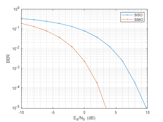
The BER curve shows a gain of 6 dB provided by the receive array.
误码率曲线显示了接收阵列提供的6 dB增益。
MISO LOS Channel
The multiple input single output (MISO) system works in a similar way. In this case, the transmitter is a 4-element ULA with half-wavelength spacing.
多输入单输出(MISO)系统以类似的方式工作。在这种情况下,发射器是具有半波长间距的4单元ULA。
txarray = phased.ULA('NumElements',4,'ElementSpacing',lambda/2);
txmipos = getElementPosition(txarray)/lambda;
misochan = scatteringchanmtx(txmipos,rxsopos,txang,rxang,g);
A line of sight MISO system achieves best SNR when the transmitter has the knowledge of the receiver and steers the beam toward the receiver. In addition, to do a fair comparison with the SISO system, the total transmitter power should be the same under both situations.
当发射端对接收端有一定的了解并将波束转向接收端时,瞄准线MISO系统可获得最佳信噪比。此外,为了与SISO系统进行公平的比较,两种情况下的发射机总功率应该是相同的。
txarraystv = phased.SteeringVector('SensorArray',txarray,...
'PropagationSpeed',c);
wt = txarraystv(fc,txang)';
ber_miso = helperMIMOBER(misochan,x,ebn0_param,wt,1)/Nsamp;
helperBERPlot(ebn0_param,[ber_siso(:) ber_simo(:) ber_miso(:)]);
legend('SISO','SIMO','MISO')
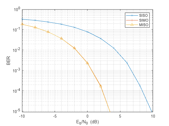
Note that with the pre-steering, the performance of MISO matches the performance of a SIMO system, gaining 6 dB in SNR. It may not be as intuitive compared to the SIMO case because the total transmit power does not increase. However, by replacing a single isotropic antenna with a 4-element transmit array, a 6 dB gain is achieved.
注意,通过预转向,MISO的性能与SIMO系统的性能相匹配,获得了6 dB的信噪比。与SIMO情况相比,它可能没有那么直观,因为总发射功率没有增加。然而,通过将单个各向同性天线替换为4单元发射阵列,可获得6 dB增益。
MIMO LOS Channel
Because a SIMO system provides an array gain from the received array and a MISO system provides an array gain from the transmit array, a MIMO system with an LOS propagation can benefit from both the transmit and receive array gain.
由于SIMO系统从接收阵列提供阵列增益,MISO系统从发射阵列提供阵列增益,具有LOS传播的MIMO系统可以从发射和接收阵列增益中受益。
Assume a MIMO system with a 4-element transmit array and a 4-element receive array.
假设一个MIMO系统有一个四元发射阵列和一个四元接收阵列。
mimochan = scatteringchanmtx(txmipos,rxmopos,txang,rxang,g);
To achieve the best SNR, the transmit array and the receive array need to be steered toward each other. With this configuration, the BER curve can be computed as
为了获得最佳信噪比,发射阵列和接收阵列需要相互引导。通过这种配置,误码率曲线可以计算为
wt = txarraystv(fc,txang)';
wr = conj(rxarraystv(fc,rxang));
ber_mimo = helperMIMOBER(mimochan,x,ebn0_param,wt,wr)/Nsamp;
helperBERPlot(ebn0_param,[ber_siso(:) ber_simo(:) ber_mimo(:)]);
legend('SISO','SIMO','MIMO')
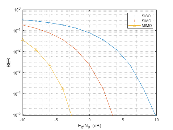
As expected, the BER curve shows that both the transmit array and the receive array contributes a 6 dB array gain, resulting in a total gain of 12 dB over the SISO case.
正如预期的那样,误码率曲线显示,发射阵列和接收阵列都贡献了6 dB的阵列增益,在SISO情况下,总增益为12 dB。
Improve SNR by Diversity Gain for Multipath Channel
利用分集增益提高多径信道的信噪比
All the channels in the previous sections are line-of-sight channels. Although such channels are found in some wireless communication systems, in general wireless communications occurs in multipath fading environments. The rest of this example explores how using arrays can help in a multipath environment.
前面部分中的所有通道都是视距通道。虽然在一些无线通信系统中可以找到这样的信道,但一般无线通信都发生在多径衰落环境中。本示例的其余部分将探讨如何在多路径环境中使用数组。
SISO Multipath Channel
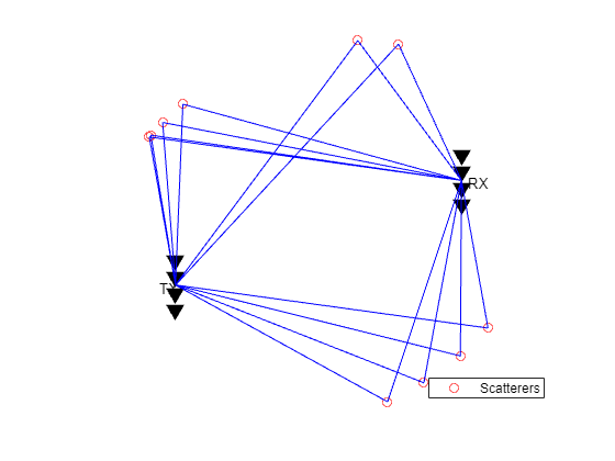
Assume there are 10 randomly placed scatterers in the channel, then there will be 10 paths from the transmitter to the receiver, as illustrated in the following figure.
假设信道中有10个随机放置的散射体,那么从发射机到接收机将有10条路径,如下图所示。
Nscat = 10;
[~,~,~,scatpos] = ...
helperComputeRandomScatterer(txcenter,rxcenter,Nscat);
helperPlotSpatialMIMOScene(txsipos,rxsopos,...
txcenter,rxcenter,scatpos);

For simplicity, assume that signals traveling along all paths arrive within the same symbol period so the channel is frequency flat.
为简单起见,假设沿着所有路径传播的信号在相同的符号周期内到达,因此信道是频率平坦的。
To simulate the BER curve for a fading channel, the channel needs to change over time. Assume we have 1000 frames and each frame has 10000 bits. The baseline SISO multipath channel BER curve is constructed as
为了模拟衰落信道的误码率曲线,信道需要随时间变化。假设我们有1000帧,每帧有10000位。所构造的基线单输入自适应多径信道误码率曲线为
Nframe = 1e3;
Nbitperframe = 1e4;
Nsamp = Nframe*Nbitperframe;
x = randi([0 1],Nbitperframe,1);
nerr = zeros(1,Nsnr);
for m = 1:Nframe
sisompchan = scatteringchanmtx(txsipos,rxsopos,Nscat);
wr = sisompchan'/norm(sisompchan);
nerr = nerr+helperMIMOBER(sisompchan,x,ebn0_param,1,wr);
end
ber_sisomp = nerr/Nsamp;
helperBERPlot(ebn0_param,[ber_siso(:) ber_sisomp(:)]);
legend('SISO LOS','SISO Multipath');

Compared to the BER curve derived from an LOS channel, the BER falls off much slower with the increase of energy per bit to noise power spectral density ratio (Eb/N0) due to the fading caused by the multipath propagation.
与LOS信道的误码率曲线相比,由于多径传播引起的衰落,随着比特能量与噪声功率谱密度比(Eb/N0)的增加,误码率下降得更慢。
SIMO Multipath Channel
As more receive antennas are used in the receive array, more copies of the received signals are available at the receiver. Again, assume a 4-element ULA at the receiver.
由于在接收阵列中使用了更多的接收天线,接收端可获得更多接收信号的副本。同样,假设在接收端有一个4单元的ULA。
The optimal combining weights can be derived by matching the channel response. Such a combining scheme is often termed as maximum ratio combining (MRC). Although in theory such scheme requires the knowledge of the channel, in practice the channel response can often be estimated at the receive array.
通过匹配信道响应,可以得到最优组合权值。这种组合方案通常被称为最大比例组合(MRC)。虽然在理论上这种方案需要了解信道,但在实践中,信道响应通常可以在接收阵列上估计出来。
nerr = zeros(1,Nsnr);
for m = 1:Nframe
simompchan = scatteringchanmtx(txsipos,rxmopos,Nscat);
wr = simompchan'/norm(simompchan);
nerr = nerr+helperMIMOBER(simompchan,x,ebn0_param,1,wr);
end
ber_simomp = nerr/Nsamp;
helperBERPlot(ebn0_param,[ber_sisomp(:) ber_simomp(:)]);
legend('SISO Multipath','SIMO Multipath');
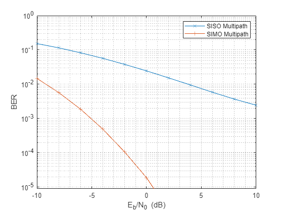
Note that the received signal is no longer weighted by a steering vector toward a specific direction. Instead, the receiving array weights in this case are given by the complex conjugate of the channel response. Otherwise it is possible that multipath could make the received signal out of phase with the transmitted signal. This assumes that the channel response is known to the receiver. If the channel response is unknown, pilot signals can be used to estimate the channel response.
注意,接收到的信号不再由指向特定方向的转向矢量进行加权。相反,在这种情况下,接收阵列权值由信道响应的复共轭给出。否则,多路径有可能使接收信号与发射信号失相。这假设信道响应是接收机已知的。在信道响应未知的情况下,可用导频信号估计信道响应。
It can be seen from the BER curve that not only the SIMO system provides some SNR gains compared to the SISO system, but the slope of the BER curve of the SIMO system is also steeper compared to the BER curve of the SISO system. The gain resulted from the slope change is often referred to as the diversity gain.
从误码率曲线可以看出,与SISO系统相比,SIMO系统不仅提供了一定的信噪比增益,而且SIMO系统的误码率曲线斜率也比SISO系统的误码率曲线更陡。由斜率变化产生的增益通常被称为分集增益。
MISO Multipath Channel
Things get more interesting when there is multipath propagation in a MISO system. First, if the channel is known to the transmitter, then the strategy to improve the SNR is similar to maximum ratio combining. The signal radiated from each element of the transmit array should be weighted so that the propagated signal can be added coherently at the receiver.
当MISO系统中存在多路径传播时,事情变得更加有趣。首先,如果发射机知道信道,那么提高信噪比的策略类似于最大比组合。从发射阵列的每个单元辐射的信号应该被加权,以便传播的信号可以在接收机上相干地添加。
nerr = zeros(1,Nsnr);
for m = 1:Nframe
misompchan = scatteringchanmtx(txmipos,rxsopos,Nscat);
wt = misompchan'/norm(misompchan);
nerr = nerr+helperMIMOBER(misompchan,x,ebn0_param,wt,1);
end
ber_misomp = nerr/Nsamp;
helperBERPlot(ebn0_param,[ber_sisomp(:) ber_simomp(:) ber_misomp(:)]);
legend('SISO Multipath','SIMO Multipath','MISO Multipath');

Note the transmit diversity gain shown in the BER curve. Compared to the SIMO multipath channel case, the performance of a MISO multipath system is not as good. This is because there is only one copy of the received signal yet the transmit power gets spread among multiple paths. It is certainly possible to amplify the signal at the transmit side to achieve an equivalent gain, but that introduces additional cost.
请注意误码率曲线中显示的发射分集增益。与SIMO多路径信道情况相比,MISO多路径系统的性能不如SIMO多路径系统。这是因为接收到的信号只有一个副本,而发射功率却分散在多个路径上。在发射端放大信号以获得等效增益当然是可能的,但这会带来额外的成本。
If the channel is not known to the transmitter, there are still ways to explore the diversity via space time coding. For example, Alamouti code is a well known coding scheme that can be used to achieve diversity gain when the channel is not known. Interested readers are encouraged to explore the Introduction to MIMO Systems example in Communications Toolbox™.
如果发射机不知道信道,仍然有方法通过时空编码来探索多样性。例如,Alamouti码是一种著名的编码方案,可用于在信道未知时实现分集增益。鼓励感兴趣的读者探索通信工具箱™中的MIMO系统介绍示例。
MIMO Multipath Channel
The rest of this example focuses on a multipath MIMO channel. In particular, this section illustrates the case where the number of scatterers in the environment is larger than the number of elements in the transmit and receive arrays. Such an environment is often termed as a rich scattering environment.
本例的其余部分主要讨论多路径MIMO通道。特别地,本节说明了环境中散射体的数量大于发射和接收阵列中元素的数量的情况。这样的环境通常被称为富散射环境。
Before diving into the specific performance measures, it is helpful to get a quick illustration of what the channel looks like. The following helper function creates a 4x4 MIMO channel where both transmitter and receiver are 4-element ULAs.
在深入研究具体的性能度量之前,快速了解通道的外观是很有帮助的。下面的辅助函数创建一个4x4 MIMO通道,其中发射器和接收器都是4单元ula。
[txang,rxang,scatg,scatpos] = ...
helperComputeRandomScatterer(txcenter,rxcenter,Nscat);
mimompchan = scatteringchanmtx(txmipos,rxmopos,txang,rxang,scatg);
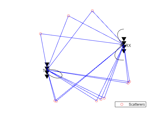
There are multiple paths available between the transmit array and the receive array because of the existence of the scatterers. Each path consists of a single bounce off the corresponding scatterer.
由于散射体的存在,在发射阵列和接收阵列之间有多条可用路径。每条路径都由对应的散射体的单个反弹组成。
helperPlotSpatialMIMOScene(txmipos,rxmopos,txcenter,rxcenter,scatpos);
There are two ways to take advantage of a MIMO channel. The first way is to explore the diversity gain offered by a MIMO channel. Assuming the channel is known, the following figure shows the diversity gain with the BER curve.
有两种方法可以利用MIMO通道。第一种方法是探索MIMO通道提供的多样性增益。假设信道是已知的,下图显示了基于误码率曲线的分集增益。
nerr = zeros(1,Nsnr);
for m = 1:Nframe
mimompchan = scatteringchanmtx(txmipos,rxmopos,Nscat);
[u,s,v] = svd(mimompchan);
wt = u(:,1)';
wr = v(:,1);
nerr = nerr+helperMIMOBER(mimompchan,x,ebn0_param,wt,wr);
end
ber_mimomp = nerr/Nsamp;
helperBERPlot(ebn0_param,[ber_sisomp(:) ber_simomp(:) ber_mimomp(:)]);
legend('SISO Multipath','SIMO Multipath','MIMO Multipath');
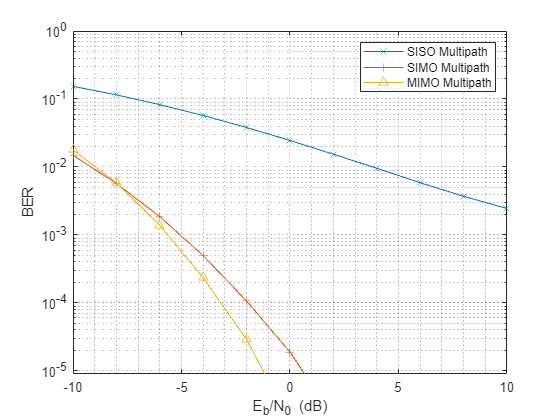
Compare the BER curve from a MIMO channel with the BER curve obtained from a SIMO system. In the multipath case, the diversity gain from a MIMO channel is not necessarily better than the diversity gain provided by a SIMO channel. This is because to obtain the best diversity gain, only the dominant mode in a MIMO channel is used yet there are other modes in the channel that are not used. So is there an alternative way to utilize the channel?
将MIMO信道的误码率曲线与SIMO系统的误码率曲线进行比较。在多路径情况下,MIMO通道提供的分集增益不一定比SIMO通道提供的分集增益更好。这是因为为了获得最佳分集增益,只使用MIMO信道中的主导模式,而信道中还有其他模式没有使用。那么有没有其他方法来利用这个渠道呢?
Improve Capacity by Spatial Multiplexing for MIMO Multipath Channel
MIMO多径信道空间复用提高容量
The answer to the previous question lies in a scheme called spatial multiplexing. The idea behind spatial multiplexing is that a MIMO multipath channel with a rich scatterer environment can send multiple data streams simultaneously across the channel. For example, the channel matrix of a 4x4 MIMO channel becomes full rank because of the scatterers. This means that it is possible to send as many as 4 data streams at once. The goal of spatial multiplexing is less about increasing the SNR but more about increasing the information throughput.
前一个问题的答案在于一种称为空间多路复用的方案。空间多路复用背后的思想是,具有丰富的散射器环境的MIMO多径信道可以同时通过信道发送多个数据流。例如,由于散射体的存在,4x4 MIMO信道的信道矩阵变成满秩。这意味着一次可以发送多达4个数据流。空间复用的目标不在于提高信噪比,而在于提高信息吞吐量。
The idea of spatial multiplexing is to separate the channel matrix to multiple mode so that the data stream sent from different elements in the transmit array can be independently recovered from the received signal. To achieve this, the data stream is precoded before the transmission and then combined after the reception. The precoding and combining weights can be computed from the channel matrix by
空间多路复用的思想是将信道矩阵分离为多种模式,以便从发射阵列中不同元素发送的数据流可以独立地从接收信号中恢复。为了实现这一点,数据流在传输前被预编码,然后在接收后进行组合。从信道矩阵中计算预编码权值和组合权值
[wp,wc] = diagbfweights(mimompchan);
To see why the combination of the precoding and combining weights can help transmit multiple data streams at the same time, examine the product of the weights and the channel matrix.
要了解为什么预编码和组合权重的组合可以帮助同时传输多个数据流,请检查权重和信道矩阵的乘积。
wp*mimompchan*wc
Note that the product is a diagonal matrix, which means that the information received by each receive array element is simply a scaled version of the transmit array element. So it behaves like multiple orthogonal subchannels within the original channel. The first subchannel corresponds to the dominant transmit and receive directions so there is no loss in the diversity gain. In addition, it is now possible to use other subchannels to carry information too, as shown in the BER curve for the first two subchannels.
请注意,乘积是一个对角矩阵,这意味着每个接收数组元素接收的信息只是发射数组元素的缩放版本。所以它就像原始通道中的多个正交子通道。第一个子信道对应于主要的发射和接收方向,因此在分集增益中没有损失。此外,现在也可以使用其他子信道来携带信息,如前两个子信道的误码率曲线所示。
Ntx = 4;
Nrx = 4;
x = randi([0 1],Nbitperframe,Ntx);
nerr = zeros(Nrx,Nsnr);
for m = 1:Nframe
mimompchan = scatteringchanmtx(txmipos,rxmopos,Nscat);
[wp,wc] = diagbfweights(mimompchan);
nerr = nerr+helperMIMOMultistreamBER(mimompchan,x,ebn0_param,wp,wc);
end
ber_mimompdiag = nerr/Nsamp;
helperBERPlot(ebn0_param,[ber_sisomp(:) ber_mimomp(:)...
ber_mimompdiag(1,:).' ber_mimompdiag(2,:).']);
legend('SISO LOS','MIMO Multipath','MIMO Multipath Stream 1',...
'MIMO Multipath Stream 2');

Although the second stream cannot provide a gain as high as the first stream as it uses a less dominant subchannel, the overall information throughput is improved. Therefore, next section measures the performance by the channel capacity instead of the BER curve.
尽管第二个流不能提供像第一个流那样高的增益,因为它使用了一个不那么占优势的子通道,但总体信息吞吐量得到了提高。因此,下一节通过信道容量而不是误码率曲线来衡量性能。
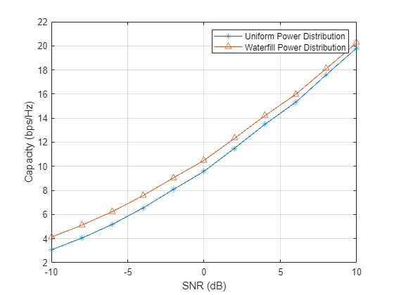
The most intuitive way to transmit data in a MIMO system is to uniformly split the power among transmit elements. However, the capacity of the channel can be further improved if the channel is known at the transmitter. In this case, the transmitter could use the waterfill algorithm to make the choice of transmitting only in the subchannels where a satisfying SNR can be obtained. The following figure shows the comparison of the system capacity between the two power distribution schemes. The result confirms that the waterfill algorithm provides a better system capacity compared to the uniform power distribution. The difference gets smaller when the system level SNR improves.
在MIMO系统中传输数据最直观的方法是在传输单元之间均匀地分配功率。然而,如果发射机知道信道,信道的容量可以进一步提高。在这种情况下,发射机可以使用注水算法来选择只在能够获得满意信噪比的子信道中发射。两种配电方案的系统容量对比如下图所示。结果表明,与均匀功率分配相比,注水算法能提供更好的系统容量。随着系统级信噪比的提高,差异逐渐减小。
C_mimo_cu = zeros(1,Nsnr);
C_mimo_ck = zeros(1,Nsnr);
Ntrial = 1000;
for m = 1:Nsnr
for n = 1:Ntrial
mimompchan = scatteringchanmtx(txmipos,rxmopos,Nscat);
N0 = db2pow(-ebn0_param(m));
[~,~,~,~,cu] = diagbfweights(mimompchan,1,N0,'uniform');
[~,~,~,~,ck] = diagbfweights(mimompchan,1,N0,'waterfill');
C_mimo_cu(m) = C_mimo_cu(m)+cu;
C_mimo_ck(m) = C_mimo_ck(m)+ck;
end
end
C_mimo_cu = C_mimo_cu/Ntrial;
C_mimo_ck = C_mimo_ck/Ntrial;
plot(ebn0_param,C_mimo_cu(:),'-*',ebn0_param,C_mimo_ck(:),'-^');
xlabel('SNR (dB)');
ylabel('Capacity (bps/Hz)');
legend('Uniform Power Distribution','Waterfill Power Distribution');
grid on;
For more details on spatial multiplexing and its detection techniques, refer to the Spatial Multiplexing example in Communications Toolbox.
有关空间多路复用及其检测技术的更多详细信息,请参阅通信工具箱中的空间多路复用示例。
From Beamforming to Precoding
从波束形成到预编码
Finally, it is worth looking at how these different ways of using arrays relate to each other. Starting from the LOS channel, as mentioned in the previous sections, the benefit provided by the array is an improvement in the SNR.
最后,值得研究一下这些使用数组的不同方式是如何相互关联的。从LOS信道开始,如前一节所述,阵列提供的好处是SNR的改进。
[~,txang] = rangeangle(rxcenter,txcenter);
[~,rxang] = rangeangle(txcenter,rxcenter);
mimochan = scatteringchanmtx(txmipos,rxmopos,txang,rxang,1);
wt = txarraystv(fc,txang)';
wr = conj(rxarraystv(fc,rxang));
helperPlotSpatialMIMOScene(txmipos,rxmopos,txcenter,rxcenter,...
(txcenter+rxcenter)/2,wt,wr)
It is clear from the sketch that in this case, the transmit and receive weights form two beams that point to each other. Thus, the array gain is achieved by the beamforming technique. On the other hand, if one tries to create a similar sketch for a MIMO channel, it looks like the following figure.
从草图中可以清楚地看出,在这种情况下,发送和接收权重形成了彼此指向的两个波束。因此,阵列增益是通过波束形成技术实现的。另一方面,如果有人试图为MIMO通道创建类似的草图,它看起来如下图所示。
[txang,rxang,scatg,scatpos] = ...
helperComputeRandomScatterer(txcenter,rxcenter,Nscat);
mimompchan = scatteringchanmtx(txmipos,rxmopos,txang,rxang,scatg);
[wp,wc] = diagbfweights(mimompchan);
helperPlotSpatialMIMOScene(txmipos,rxmopos,txcenter,rxcenter,...
scatpos,wp(1,:),wc(:,1))
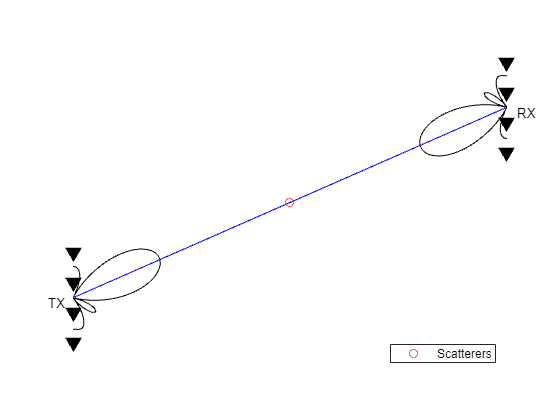
Note that the figure only depicts the pattern for the first data stream but nevertheless it is clear that the pattern no longer necessarily has a dominant main beam. However, if the number of scatterers is reduced to one, then the scene becomes
请注意,该图仅描述了第一个数据流的模式,但很明显,该模式不再一定具有主导主梁。然而,如果散射体的数量减少到一个,那么场景就变成了
[txang,rxang,scatg,scatpos] = ...
helperComputeRandomScatterer(txcenter,rxcenter,1);
mimompchan = scatteringchanmtx(txmipos,rxmopos,txang,rxang,scatg);
[wp,wc] = diagbfweights(mimompchan);
helperPlotSpatialMIMOScene(txmipos,rxmopos,txcenter,rxcenter,...
scatpos,wp(1,:),wc(:,1))
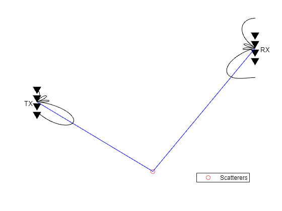
Therefore, the LOS channel case, or more precisely, the one scatterer case, can be considered as a special case of the precoding. When there is only one path available between the transmit and receive arrays, the precoding degenerates to a beamforming scheme.
因此,LOS信道情况,或者更准确地说,单散射体情况,可以被认为是预编码的一种特殊情况。当发送阵列和接收阵列之间只有一条可用路径时,预编码退化为波束形成方案。
Summary
This example explains how array processing can be used to improve the quality of a MIMO wireless communication system. Depending on the nature of the channel, the arrays can be used to either improve the SNR via array gain or diversity gain, or improve the capacity via spatial multiplexing. The example also shows how to use functions like scatteringchanmtx and diagbfweights to simulate those scenarios. For more information on MIMO systems modeling, interested readers may refer to examples provided in Communications Toolbox.
本例解释了如何使用阵列处理来提高MIMO无线通信系统的质量。根据信道的性质,阵列既可以通过阵列增益或分集增益来提高信噪比,也可以通过空间复用来提高容量。该示例还展示了如何使用scatteringchanmtx和diagbfweights等函数来模拟这些场景。有关MIMO系统建模的更多信息,感兴趣的读者可以参考通信工具箱中提供的示例。
Reference
[1] David Tse and Pramod Viswanath, Fundamentals of Wireless Communications, Cambridge, 2005
[2] Arogyswami Paulraj, Introduction to Space-Time Wireless Communication, Cambridge, 2003
Copyright 2016-2018 The MathWorks, Inc.


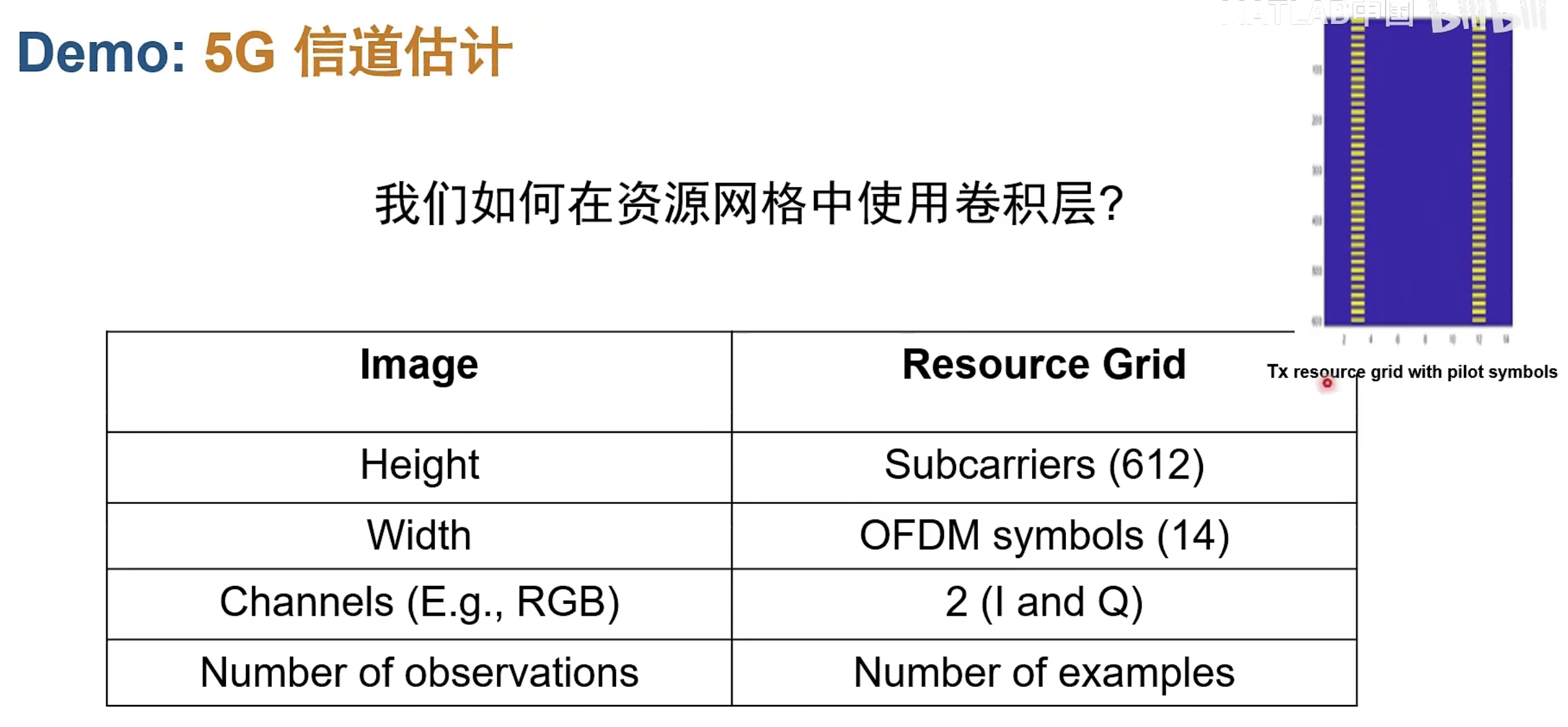
信道估计:参考信号估计、盲估计、半盲估计
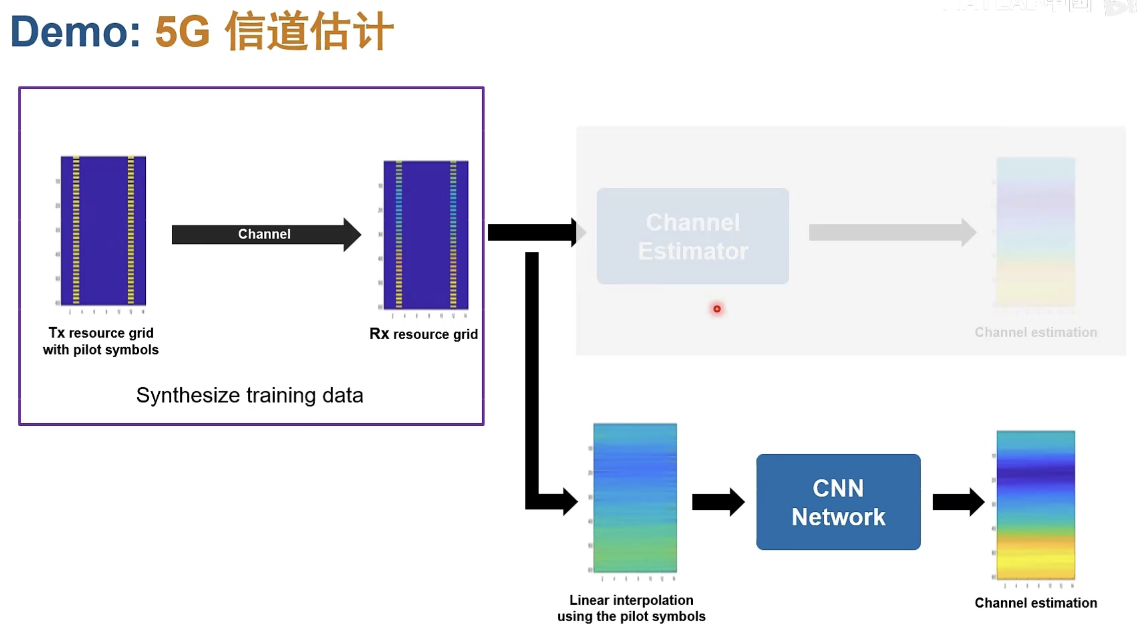
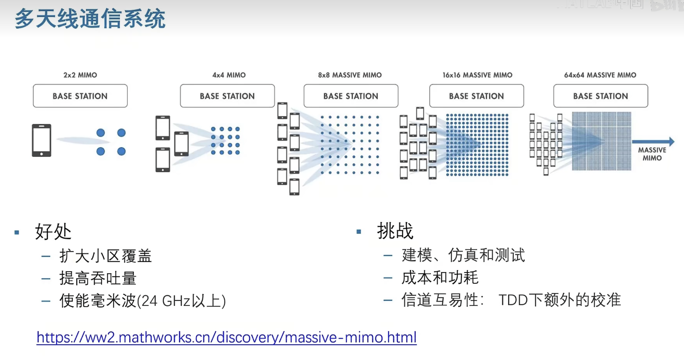
天线数目的增加,频率范围的变化,整个环境的变化,信道的变异性也有所增加;
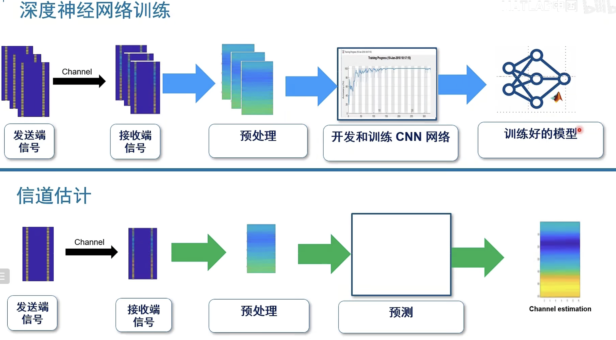
在通信中利用AI来训练信道估计器,
纵轴在频域上包含了许多子载波,横轴在时域上包含了n个OFDM符号。