一、基础知识之(交换机的)虚接口 vlan
1. 端口加入vlan
[S1]interface GigabitEthernet 0/0/1
[S1-GigabitEthernet0/0/1]port link-type access 接口模式配置为access模式
[S1-GigabitEthernet0/0/1]port default vlan 2 接口加入 vlan2
<S1>display vlan 查看当前配置的 vlan
2.多个端口加入vlan
[S1]port-group 1 创建端口组
[S1-port-group-1]group-memberg0/0/1 to g0/0/10添加端口组成员
[S1-port-group-1]port link-typeaccess
[S1-port-group-1]portdefault vlan 2
3.Trunk配置
[Huawei]interfaceGigabitEthernet 0/0/5
[Huawei-GigabitEthernet0/0/5]portlink-type trunk 配置接口模式为truk模式
[Huawei-GigabitEthernet0/0/5]porttrunk allow-pass vlan all 配置trunk链路允许通过的vlan
4.配置 hybrid
[sw1]vlan batch 10 //创建vlan10
[sw1] interface g0/0/1 //进入接口g0/0/1
[sw1-g0/0/1]port link-type hybrid //将接口改为hybrid模式
[sw1-g0/0/1]port hybrid pvid vlan 10 //配置接口的pvid为10
[sw1-g0/0/1]port hybrid untagged vlan 10
//接口发送数据帧时,允许vlan10的数据帧通过,并且剥离数据帧中的vlan10标签
[sw1] interface g0/0/2 //进入接口g0/0/2
[sw1-g0/0/2]port link-type hybrid //将接口改为hybrid模式
[sw1-g0/0/2]port hybrid pvid vlan 10 //配置接口的pvid为10
[sw1-g0/0/2]port hybrid untagged vlan 10
//接口发送数据帧时,允许vlan10的数据帧通过,并且剥离数据帧中的vlan10标签
验证与测试:
pc1 ping pc2 可以互通
二,需求变化之路由交换配置
1.快速生成树-负载均衡
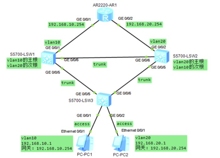
需求
- PC1属于 vlan 10 ,IP地址为 192.168.10.1/24,网关为 192.168.10.254
- PC2属于 vlan 20 ,IP地址为 192.168.20.1/24,网关为 192.168.20.254
- 确保PC1与PC2互通
- 合理配置 MSTP ,确保PC1与PC2之间的互通路径是最优的
配置步骤:
- 配置PC的IP地址
- 在所有的交换机中都创建vlan10和vlan20
- 交换机连接PC的接口设置为access模式,并加入指定的vlan
- 交换机和交换机互联的接口设置trunk模式,并允许vlan10和vlan20 通过
- 在所有的交换机中配置MSTP,所有交换机中的MSTP配置都要完全相同
- 指定SW1为vlan10的主根, vlan20的备根
- 指定SW2为vlan20的主根, vlan10的备根
- 配置路由器接口的IP地址
命令:
 1 S1、S2、S3创建vlan并配置连接交换机的端口为trunk
 2 [S1]VLAN batch 10 20
 3 [S1]port-group 1
 4 [S1-port-group-1]group-member G0/0/5 G0/0/6
 5 [S1-port-group-1]port link-type trunk
 6 [S1-GigabitEthernet0/0/5]port trunk allow-pass vlan ALL
 7
 8 [S2]VLAN batch 10 20
 9 [S2]port-group 1
10 [S2-port-group-1]group-member G0/0/5 G0/0/6
11 [S2-port-group-1]port link-type trunk
12 [S2-GigabitEthernet0/0/5]port trunk allow-pass vlan ALL
13
14 [S3]VLAN batch 10 20
15 [S3]port-group 1
16 [S3-port-group-1]group-member G0/0/5 G0/0/6
17 [S3-port-group-1]port link-type trunk
18 [S3-GigabitEthernet0/0/5]port trunk allow-pass vlan ALL
19
20 S1、S2、S3配置MSTP区域并激活
21 [S1]stp mode mstp 启用MSTP协议
22 [S1]stp region-configuration 创建区域
23 [S1-mst-region]region-name ntd 定义区域名为ntd
24 [S1-mst-region]instance 1 vlan 10 指定vlan与实例的对应关系
25 [S1-mst-region]instance 2 vlan 20
26 [S1-mst-region]active region-configuration 激活区域配置
27
28
29 [S2]stp mode mstp 启用MSTP协议
30 [S2]stp region-configuration 创建区域
31 [S2-mst-region]region-name ntd 定义区域名为ntd
32 [S2-mst-region]instance 1 vlan 10 指定vlan与实例的对应关系
33 [S2-mst-region]instance 2 vlan 20
34 [S2-mst-region]active region-configuration 激活区域配置
35
36 [S3]stp mode mstp 启用MSTP协议
37 [S3]stp region-configuration 创建区域
38 [S3-mst-region]region-name ntd 定义区域名为ntd
39 [S3-mst-region]instance 1 vlan 10 指定vlan与实例的对应关系
40 [S3-mst-region]instance 2 vlan 20
41 [S3-mst-region]active region-configuration 激活区域配置
42
43 3)配置S1为vlan10的主根、vlan20的次根网桥并查看配置
44 [S1]stp instance 1 priority 4096
45 [S1]stp instance 2 priority 8192
46
47 4)配置S2为vlan20的主根、vlan10的次根根网桥并查看配置
48 [S2]stp instance2 priority 4096
49 [S2]stp instance 1 priority 8192
50
51 5)配置PC1加入vlan10、PC2加入vlan20**
52 [S3]interface GigabitEthernet 0/0/1
53 [S3-GigabitEthernet0/0/1]port link-type access
54 [S3-GigabitEthernet0/0/1]port default vlan 10
55 [S3]interface GigabitEthernet 0/0/2
56 [S3-GigabitEthernet0/0/2]port link-type access
57 [S3-GigabitEthernet0/0/2]port default vlan 20
58
59 **6)配置S1与路由相连的接口加入vlan10**
60 [S1]interface GigabitEthernet 0/0/1
61 [S1-GigabitEthernet0/0/1]port link-type access
62 [S1-GigabitEthernet0/0/1]port default vlan 10
63
64 **7)配置S2与路由相连的接口加入 vlan20**
65 [S2]interface GigabitEthernet 0/0/2
66 [S2-GigabitEthernet0/0/2]port link-type access
67 [S2-GigabitEthernet0/0/2]port default vlan 20
68
69 **8)配置路由器接口IP**
70 [R1]interface GigabitEthernet 0/0/1
71 [R1-GigabitEthernet0/0/1]ip address 192.168.10.254 24
72 [R1]interface GigabitEthernet 0/0/2
73 [R1-GigabitEthernet0/0/2]ip address 192.168.20.254 24
74
75 **9)测试与验证**
76 pc1 ping pc2 通
77
78 **10)查看验证**
<SW3>display stp brief
查看S1的instance 1 g0/0/5 g0/0/6都是指定接口
查看S2的instance 2 g0/0/5 g0/0/6都是指定接口
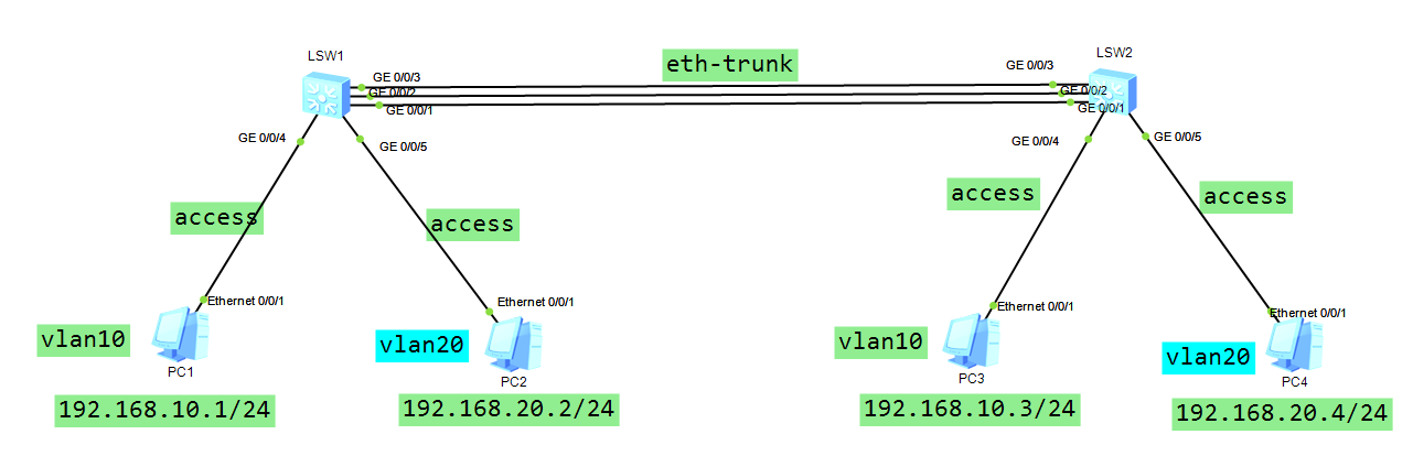
2.链路聚合的工作模式 lacp
1)LACP模式也称为M:N模式
2)M条活动链路,N条备份链路
3)当活动链路出现故障时,备份链路才进行转发
配置步骤
1)PC配置IP地址
2)所有的交换机都创建vlan10 20
3) 交换机和pc互联的接口做成access ,并且加入指定的vlan
4)设置交换机的lacp 优先级,确定主动端设备
5) 配置链路聚合
-创建链路聚合组,组号为1
-配置链路聚合的工作模式lacp
-在链路聚合中添加成员接口
-设置接口trunk模式
-设置活动端口(活动链路)的上限阈值为2
-开启lacp 抢占
 1 SW1配置:
配置好相应交换机的端口(4,5)模式以及 vlan ...
10 [SW1]lacp priority 100    //配置lacp的系统优先级(越小越优先)
11 [SW1]interface eth-trunk 1   //创建链路聚合组1
12 [SW1-Eth-Trunk1]mode lacp-static   //链路聚合的工作模式是lacp
13 [SW1-Eth-Trunk1]trunkport  g 0/0/1  to  0/0/3   //在链路聚合组中添加成员接口
14 [SW1-Eth-Trunk1]port link-type trunk     //设置trunk模式
15 [SW1-Eth-Trunk1]port trunk allow-pass vlan 10 20    //允许vlan10 20 流量通过
16 [SW1-Eth-Trunk1]max active-linknumber 2   //设置活动端口的上限阈值为2
17 [SW1-Eth-Trunk1]lacp preempt enable   //开启抢占功能
18
19 SW2配置:
20 [SW2]vlan batch  10  20
配置好相应交换机的端口(4,5)模式以及 vlan ....
28 [SW2]int eth-trunk 1
29 [SW2-Eth-Trunk1]mode lacp-static
30 [SW2-Eth-Trunk1]trunkport g 0/0/1 to 0/0/3
31 [SW2-Eth-Trunk1]port link-type trunk
32 [SW2-Eth-Trunk1]port trunk allow-pass vlan 10 20


36 测试与验证:
37 pc1 ping  pc3  通
38 pc1 ping  pc4  通
39
40 [SW1]display eth-trunk 1    //显示链路聚合信息
41 Preempt Delay Time: 30     //抢占延迟30秒
42 System Priority: 100     //系统优先级:100
43 Least Active-linknumber: 1  Max Active-linknumber: 2 (最大活跃链路:2)
44 Operate status: up  (状态:up)
45 --------------------------------------------------------------------------------
46 ActorPortName          Status   PortType PortPri  PortNo
47 GigabitEthernet0/0/1   Selected 1GE      32768    2  (lacp给本段接口分配的序号)
48 GigabitEthernet0/0/2   Selected 1GE      32768    3
49 GigabitEthernet0/0/3   Unselect 1GE      32768    4
50
51 备注:  Selected :被选择的接口
52        Unselect :位被选择的接口
53        PortPri : 端口lacp优先级
54        PortNo  : lacp 协议给成员口分配的编号
55
56 Partner: (本段接口所连接的对端设备接口信息)
57 --------------------------------------------------------------------------------
58 ActorPortName          SysPri   SystemID        PortPri  PortNo
59 GigabitEthernet0/0/1   32768    4c1f-ccef-5a42  32768    4 (lacp给对端接口分配的序号)
60 GigabitEthernet0/0/2   32768    4c1f-ccef-5a42  32768    5
61 GigabitEthernet0/0/3   32768    4c1f-ccef-5a42  32768    6
链路聚合综合实验

   1 [S1]interface Eth-Trunk 1
  3 [SW1-Eth-Trunk1]mode lacp-static
  5 [S1-Eth-Trunk1]trunkportGigabitEthernet 0/0/3 0/0/4  //注意有空格
  7 [S1-Eth-Trunk1]port link-typetrunk
  9 [S1-Eth-Trunk1]port trunk allow-pass vlan all

 13 [S2]interface Eth-Trunk 1
 15 [SW2-Eth-Trunk1]mode lacp-static
 17 [S2-Eth-Trunk1]trunkportGigabitEthernet 0/0/5 0/0/6
 19 [S2-Eth-Trunk1]port link-typetrunk
 21 [S2-Eth-Trunk1]port trunk allow-pass vlan ALL

 25 [S3]interface Eth-Trunk 1
 27 [SW3-Eth-Trunk1]mode lacp-static
 29 [S3-Eth-Trunk1]trunkportGigabitEthernet 0/0/3 0/0/4
 31 [S3-Eth-Trunk1]port link-typetrunk
 33 [S3-Eth-Trunk1]port trunk allow-pass vlan all

 37 [S4]interface Eth-Trunk 1
 39 [SW4-Eth-Trunk1]mode lacp-static
 41 [S4-Eth-Trunk1]trunkportGigabitEthernet 0/0/5 0/0/6
 43 [S4-Eth-Trunk1]port link-typetrunk
 45 [S4-Eth-Trunk1]port trunk allow-pass vlan all

 49 [S5]interface Eth-Trunk 1
 51 [SW5-Eth-Trunk1]mode lacp-static
 53 [S5-Eth-Trunk1]trunkportGigabitEthernet 0/0/3 0/0/4
 55 [S5-Eth-Trunk1]port link-typetrunk
 57 [S5-Eth-Trunk1]port trunkallow-pass vlan all
 59 [S5]interface Eth-Trunk 2
 61 [SW5-Eth-Trunk2]mode lacp-static
 63 [S5-Eth-Trunk2]trunkportGigabitEthernet 0/0/5 0/0/6
 65 [S5-Eth-Trunk2]port link-typetrunk
 67 [S5-Eth-Trunk2]port trunkallow-pass vlan all
 69 [S5]interface Eth-Trunk 3
 71 [SW5-Eth-Trunk3]mode lacp-static
 73 [S5-Eth-Trunk3]trunkportGigabitEthernet 0/0/7 0/0/8
 75 [S5-Eth-Trunk3]port link-typetrunk
 77 [S5-Eth-Trunk3]port trunkallow-pass vlan all

 81 [S6]interface Eth-Trunk 1
 83 [SW6-Eth-Trunk1]mode lacp-static
 85 [S6-Eth-Trunk1]trunkportGigabitEthernet 0/0/5 0/0/6
 87 [S6-Eth-Trunk1]port link-typetrunk
 89 [S6-Eth-Trunk1]port trunkallow-pass vlan all
 91 [S6]interface Eth-Trunk 2
 93 [SW6-Eth-Trunk2]mode lacp-static
 95 [S6-Eth-Trunk2]trunkportGigabitEthernet 0/0/3 0/0/4
 97 [S6-Eth-Trunk2]port link-typetrunk
 99 [S6-Eth-Trunk2]port trunkallow-pass vlan all
101 [S6]interface Eth-Trunk 3
103 [SW6-Eth-Trunk3]mode lacp-static
105 [S6-Eth-Trunk3]trunkportGigabitEthernet 0/0/7 0/0/8
107 [S6-Eth-Trunk3]port link-typetrunk
109 [S6-Eth-Trunk3]port trunk allow-pass vlan all
110
111 ## 2)S1-S6创建vlan
112
113 [S1]vlan batch 10 20
115 [S2]vlan batch 10 20
117 [S3]vlan batch 10 20
119 [S4]vlan batch 10 20
121 [S5]vlan batch 10 20
123 [S6]vlan batch 10 20
124
125 ## 3)S1-S4端口加入vlan
126
127 [S1]interface GigabitEthernet0/0/1
129 [S1-GigabitEthernet0/0/1]portlink-type access
131 [S1-GigabitEthernet0/0/1]port default vlan 10

135 [S2]interface GigabitEthernet0/0/1
137 [S2-GigabitEthernet0/0/1]portlink-type access
139 [S2-GigabitEthernet0/0/1]port default vlan 20

143 [S3]interface GigabitEthernet0/0/1
145 [S3-GigabitEthernet0/0/1]portlink-type access
147 [S3-GigabitEthernet0/0/1]port default vlan 10

151 [S4]interface GigabitEthernet0/0/1
153 [S4-GigabitEthernet0/0/1]portlink-type access
155 [S4-GigabitEthernet0/0/1]port default vlan 20